2018-02-17
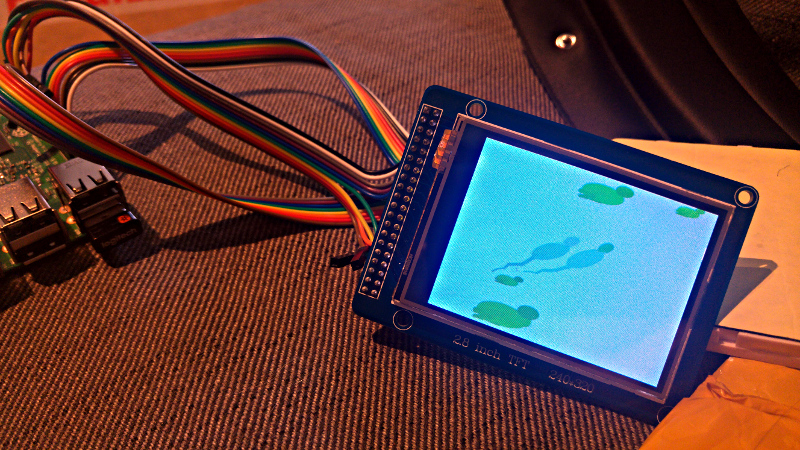
Connecting a no-name 2.8 inch, 240x320 TFT LCD panel to a Raspberry Pi
Tiny TFT panels
I needed a small display for a little project (showing some animations in my office window), and none of the electronics stores nearby had anything suitable, so I ended up digging out an (as yet unused) LCD module I bought off Ebay a few years ago.
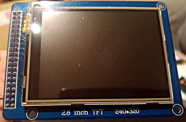
It’s a cheap non-branded panel from China (I paid USD 10.95 back in 2014), the only markings being “2.8 inch TFT 240x320” and “V1.1”. The listing said “2.8 inch 1.8” TFT LCD module Display ILI9325 with touch panel SD card 240x320” (the actual panel is 2.8”, not 1.8”), and no documentation was provided. You can still find a bunch of them on Ebay for roughly the same price.
I knew I’d gotten my other cheap panel (a 2.4” panel, also using the ILI9325 chip) working with a Raspberry Pi back in the day, but I don’t think I’ve tried this one before, so some exploration was needed to find the right connections and drivers and so on.
This panel has a 40-pin connector which you’ll find on a lot of tiny LCDs (there’s also ready made Chinese shields for interfacing with Arduino and so on). Initial investigations led me to ElectroDragon, whose pages describe panels that are almost exactly like mine (except they don’t have a 2.8” panel). But the pins and voltages seem correct: RS (data/command), WR (write), CS (chip select), REST (reset) and the data pins (DB00–DB15) need to be connected to the GPIO pins on the Raspberry Pi.
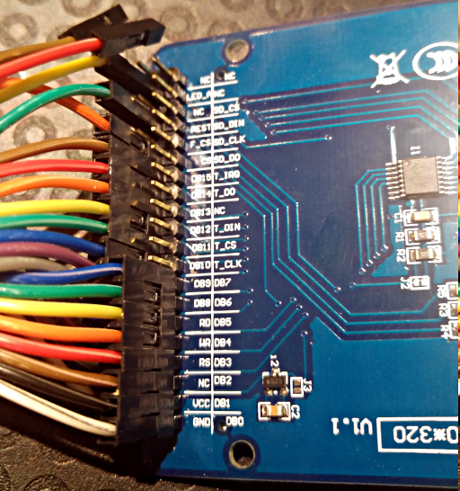
The ElectroDragon page also has this useful info “Module the user through the back of the PCB J3 pad set 8/16 bit interface, shorting J3 pad module in 16-bit mode, not less then work in 8-bit mode, module shipments default OPEN, which is shipped”. My panel has an open J3 on the back, which makes me think it’s supposed to work in 8 bit mode. It also says that “The default is 8-bit interface, 8-bit mode, only 8 (DB8-DB15, DB0-DB7 ground or to unsettled to connect).” which might mean that the 8-bit bus should be connected to DB8–DB15 rather than to DB00–DB07 (as you might expect).
Anyway, it turns out there’s a nice Linux framebuffer driver for small
LCDs: fbtft. The closest panel
on the supported device
list is itdb28,
for which the default pin wiring seems to be
gpios=reset:17,dc:1,wr:0,cs:21,db00:9,db01:11,db02:18,db03:23,db04:24,db05:25,db06:8,db07:7. It’s
been a long time since last time I did Raspberry Pi stuff (Pis back
then had 26 pins rather than 40), but fortunately there are now nice
online overviews of the Pi GPIO pins. I’m still
a bit uncertain about why the GPIO pins from the BroadCom chip seem to
be somewhat arbitrarily connected to the Pi pins (probably something
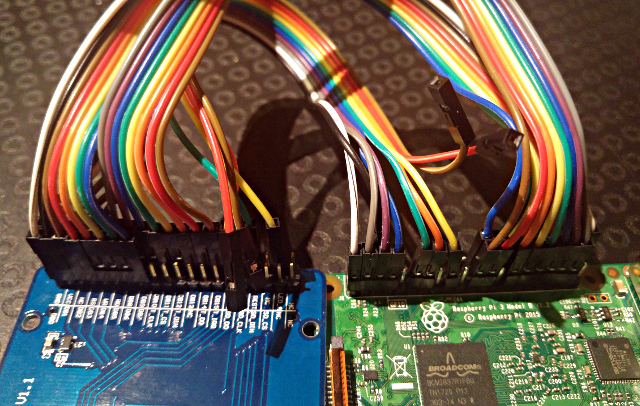
to do with PCB layout or something). Anyway, with all the ground pins
scattered around, there’s no chance of wiring up the data bus with a
single 8-pin cable, rather than individual wires.
So, I wire up the panel, boot up the Pi, and try the suggested driver:
modprobe fbtft_device name=itdb28 gpios=reset:17,dc:1,wr:0,cs:21,db00:9,db01:11,db02:18,db03:23,db04:24,db05:25,db06:8,db07:7,led:4
This is supposed to initialize the panel and set up a framebuffer
device (in /dev/fb1 – /dev/fb0 is connected to the built-in HDMI
output). I got some handy tips from this
blog,
including the suggestion to test the panel with this
giraffe.
tail --bytes 153600 giraffe.565 > /dev/fb1
Anyway, neither the driver loading nor the giraffe had any effect
(apart from the backlight turning on when I connect LED_A to 3.3V). So,
I tried:
- Connecting db00–db07 on the driver side to DB08–DB15 (as suggested
by ElectroDragon), and to DB00–DB07 (which is what I’d think by
default). (In order to try the driver with different options, it
should be unloaded first using
sudo rmmod fb_ili9325; sudo rmmod fbtft_device.) - Double-checking the connections, and using different pins on the Raspberry Pi.
- Following the directions for ITDB02-2.8 more closely, including reading the datasheets and such – and using 5V VCC (which turns out to not be right, so don’t try that! fortunately, no damage done).
- Connecting all 16 data pins, and listing them on the
modprobecommand line. - Getting really annoyed that most of the panel docs I could find never mentioned any specifics on the meaning of the jumpers on the back of the card.
- Seriously considering programming the GPIO pins directly just to see if I could get the panel to respond.
The “TFT01-2.8”
Finally, I went through all the similar-looking panels on Ebay, and finally found out that it’s most likely set to a 16-bit bus by default (rather than the 8 bits that seem more common), and it’s probably a “TFT01-2.8” panel (docs still don’t say anything sensible about the jumpers and whether they may or may not be set to 16-bit mode).
Armed with this knowledge, I studied the
fbtft_device docs
again an finally found the buswidth option. Yay! My panel is
probably not covered by the standard drivers, and should be set up
with the custom option:
sudo modprobe fbtft_device custom name=fb_ili9325 buswidth=16 ...
This had an effect! The panel turned a flickering greyish instead of
white. Unfortunately, even trying different variations of options
didn’t really help getting the panel past the flickering stage. One
of the Ebay entires directed me to the CTE28 driver for the
UTFT library
– so I also tried the initialization command sequence they used.
Getting ready to give up, I though I’d try one more thing: rewire it all to use “sensible” pins on the Raspberry Pi (i.e., keep related stuff close together, so the wiring is less messy). This probably doesn’t really matter, but it turned out to make a difference: the panel was finally initialized correctly, and I could even see something when I tried the giraffe picture. Probably, I had messed up some of the pins at some point… Giraffe was still a bit mangled, but that was fixed by rotating the display. The final, working configuration turned out to be:
sudo modprobe fbtft_device name=fb_ili9325 custom rotate=90 bgr=1 \
   buswidth=16 width=240 height=320 \
   gpios=reset:17,dc:2,wr:3,cs:27,db00:21,db01:20,db02:16,db03:12,db04:1,db05:7,db06:8,db07:25,db08:26,db09:19,db10:13,db11:6,db12:5,db13:0,db14:11,db15:9 \
   init=-1,0xE5,0x78F0,-1,0x01,0x0100,-1,0x02,0x0200,-1,0x03,0x1030,-1,0x04,0x0000,-1,0x08,0x0207,-1,0x09,0x0000,-1,0x0A,0x0000,-1,0x0C,0x0000,-1,0x0D,0x0000,-1,0x0F,0x0000,-1,0x10,0x0000,-1,0x11,0x0007,-1,0x12,0x0000,-1,0x13,0x0000,-1,0x07,0x0001,-2,200,-1,0x10,0x1690,-1,0x11,0x0227,-2,50,-1,0x12,0x000D,-2,50,-1,0x13,0x1200,-1,0x29,0x000A,-1,0x2B,0x000C,-2,50,-1,0x20,0x0000,-1,0x21,0x0000,-1,0x30,0x0000,-1,0x31,0x0404,-1,0x32,0x0003,-1,0x35,0x0405,-1,0x36,0x0808,-1,0x37,0x0407,-1,0x38,0x0303,-1,0x39,0x0707,-1,0x3C,0x0504,-1,0x3D,0x0808,-1,0x50,0x0000,-1,0x51,0x00EF,-1,0x52,0x0000,-1,0x53,0x013F,-1,0x60,0xA700,-1,0x61,0x0001,-1,0x6A,0x0000,-1,0x80,0x0000,-1,0x81,0x0000,-1,0x82,0x0000,-1,0x83,0x0000,-1,0x84,0x0000,-1,0x85,0x0000,-1,0x90,0x0010,-1,0x92,0x0000,-1,0x07,0x0133,-3
Without the custom init the colors are a bit off (lighter than
expected) – probably this should be adjusted by the gamma option,
rather than overriding init.
A working setup
The pin connections I’m using are:
 TFT   GPIO  (RPi)
--------------------------------------
 GND     –   ( 6)   # GND
 VCC     –   ( 1)   # 3.3V
 LED_A   –   (17)   # 3.3V
 REST   17   (11)   # Reset
 RS      2   ( 3)   # Data/Command (DC)
 WR      3   ( 5)   # Write
 CS     27   (13)   # Chip select
 DB00   21   (40)   # 16-bit bus
 DB01   20   (38)
 DB02   16   (36)
 DB03   12   (32)
 DB04    1   (28)
 DB05    7   (26)
 DB06    8   (24)
 DB07   25   (22)
 DB08   26   (37)
 DB09   19   (35)
 DB10   13   (33)
 DB11    6   (31)
 DB12    5   (29)
 DB13    0   (27)
 DB14   11   (23)
 DB15    9   (21)
In order to have the panel start automatically on boot, put the driver
options in a new file /etc/modprobe.d/fbtft.conf:
options fbtft_device rotate=90 fps=20 custom bgr=1 buswidth=16 width=240 height=320 name=fb_ili9325 gpios=reset:17,dc:2,wr:3,cs:27,db00:21,db01:20,db02:16,db03:12,db04:1,db05:7,db06:8,db07:25,db08:26,db09:19,db10:13,db11:6,db12:5,db13:0,db14:11,db15:9 init=-1,0xE5,0x78F0,-1,0x01,0x0100,-1,0x02,0x0200,-1,0x03,0x1030,-1,0x04,0x0000,-1,0x08,0x0207,-1,0x09,0x0000,-1,0x0A,0x0000,-1,0x0C,0x0000,-1,0x0D,0x0000,-1,0x0F,0x0000,-1,0x10,0x0000,-1,0x11,0x0007,-1,0x12,0x0000,-1,0x13,0x0000,-1,0x07,0x0001,-2,200,-1,0x10,0x1690,-1,0x11,0x0227,-2,50,-1,0x12,0x000D,-2,50,-1,0x13,0x1200,-1,0x29,0x000A,-1,0x2B,0x000C,-2,50,-1,0x20,0x0000,-1,0x21,0x0000,-1,0x30,0x0000,-1,0x31,0x0404,-1,0x32,0x0003,-1,0x35,0x0405,-1,0x36,0x0808,-1,0x37,0x0407,-1,0x38,0x0303,-1,0x39,0x0707,-1,0x3C,0x0504,-1,0x3D,0x0808,-1,0x50,0x0000,-1,0x51,0x00EF,-1,0x52,0x0000,-1,0x53,0x013F,-1,0x60,0xA700,-1,0x61,0x0001,-1,0x6A,0x0000,-1,0x80,0x0000,-1,0x81,0x0000,-1,0x82,0x0000,-1,0x83,0x0000,-1,0x84,0x0000,-1,0x85,0x0000,-1,0x90,0x0010,-1,0x92,0x0000,-1,0x07,0x0133,-3
and add fbtft_device to /etc/modules.
X11 Setup
To make it work with X11, tell the X server to use /dev/fb1. My
Raspberry Pi setup already had a framebuffer configuration in
/usr/share/X11/xorg.conf.d/99-fbturbo.conf. I copied it to
/usr/share/X11/xorg.conf.d/98-fbturbo-tft.conf and modified it to look
like this:
Section "Device"
        Identifier      "TFT01-2.8 ILI9325 LCD"
        Driver          "fbturbo"
        Option          "fbdev" "/dev/fb1"

        #Option          "SwapbuffersWait" "true"
EndSection

Section "Screen"
	Identifier	"TFT01-2.8 240x320 LCD"
	SubSection "Display"
		Depth	16
		Weight	5 6 5
	EndSubSection
EndSection

Section "ServerLayout"
	Identifier	"TFT01-2.8"
	Screen		"TFT01-2.8 240x320 LCD"
EndSection
Also, in order to make it possible to run startx via SSH, I modified
/etc/X11/Xwrapper.config to say allowed_users=anybody.
As long as it’s named 98-fbturbo-tft.conf the TFT will be used by
default rather than the HDMI output specified in
99-fbturbo.conf (the lowest number is the default). Alternatively, it can be specified explicitly via
the -layout option: startx -- -layout TFT01-2.8.
If you add a ServerLayout and Screen section to 99-fbturbo.conf,
you can also start X on the HDMI output. Mine looks like this:
Section "Device"
        Identifier      "FB"
        Driver          "fbturbo"
        Option          "fbdev" "/dev/fb0"

        Option          "SwapbuffersWait" "true"
EndSection
Section "Screen"
	Identifier	"FB-HDMI"
	Device "FB"
EndSection

Section "ServerLayout"
	Identifier	"HDMI"
	Screen		"FB-HDMI"
EndSection
(You could even run a single desktop across both displays at once, by
listing multiple screens in ServerLayout.)
For now, my Pi doesn’t automatically boot into desktop mode on the LCD panel – but if I’m going to use it to display cool stuff, I should of course set it up to start X11 at boot time, and run whatever code I want (duckpond with jumping frogs, for example…)
Other things
Booting with the console on the TFT display
This is apparently also possible, but I haven’t tried it yet.
Touch input
Haven’t tried this either, yet. Touch functionality seems to use 5 pins, so it should still fit on the 40-pin modern Pis – we’re currently using 16 pins for data and 4 for control, out of 28 GPIO pins (the other 12 Pi pins are ground and power).
tags: electronics - rpi